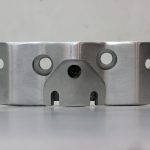
This post is about indicators. I started from making housings. I made some drawings and gave them along with stainless steel rod of suitable diameter to turner. After I received result I had to do some sandpapering and polishing. Here is final result: four housings for four indicators.
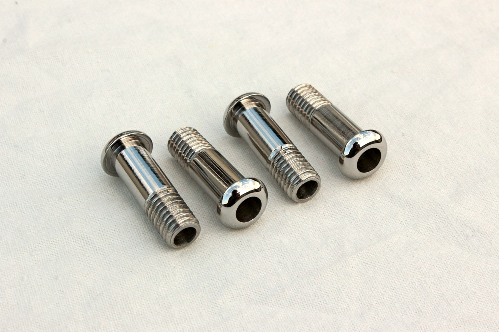
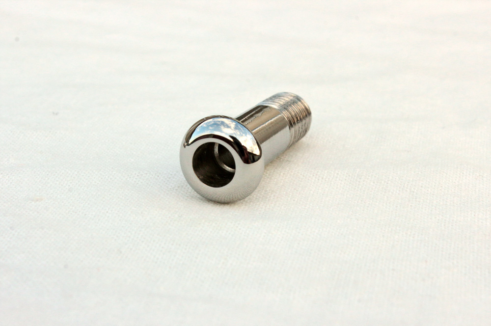
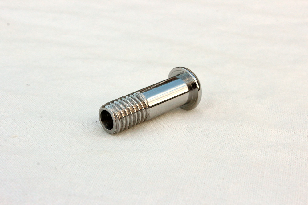
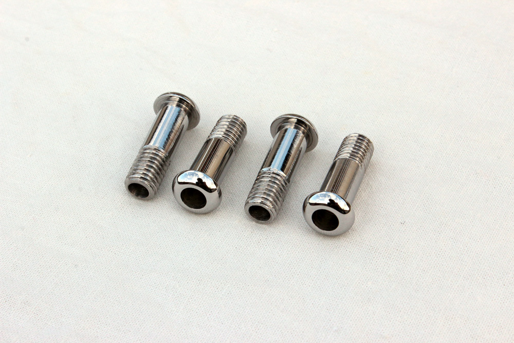 According to my plan each of them has hole cut- through, this hole has diameter of 6mm in upper part of “bolt” and 5mm in lower.
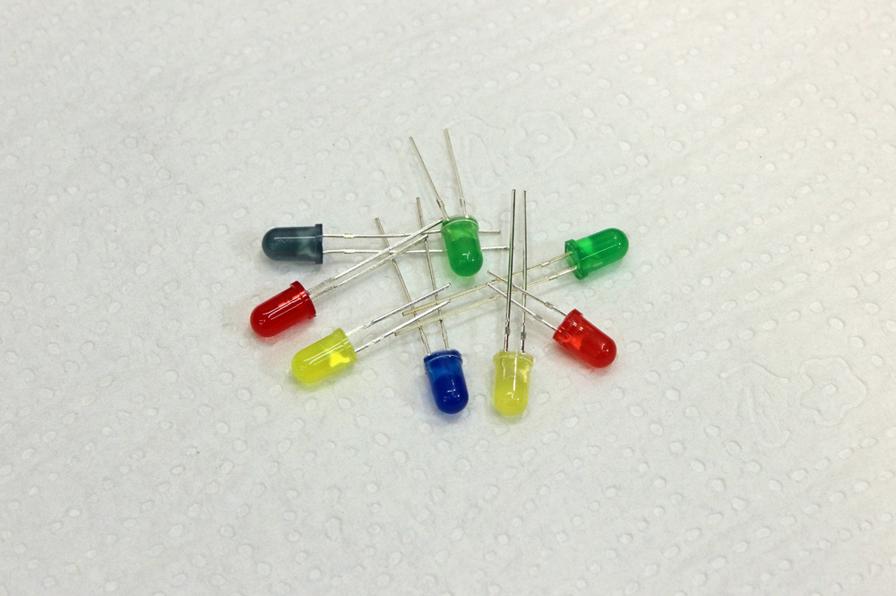
 The thing is 5mm LEDs has 6mm flange. Thus LEDS might be put into the bolt, but they couldn’t be dragged through. I chose 5mm LEDs with diffused lenses:
 Let’s add some resistors to them.
 Resistors are essential for the work of LEDs. LED of this kind will work for a long time if only current wouldn’t exceed 20mA. And resistor regulates current. There is no need in rocket science to calculate the value of resistor which will regulate current to suitable parameters. All we need is Ohm’s law which states that I=V/R. With possible peak in 14.5V in motorcycle electrical system, 2.5V of LED consuming and 20mA of suitable current we easily could calculate that “safe” resistor will have value of 600 Ohm. On practice, however, we’ll find out that yellow, green, blue and red LEDs even from same batch would have different brightness, being connected through identical resistors to same source of voltage. The dullest would be green, yellow and red would be brighter than green, while blue would burn your eyes. So after some experiments I chose resistor of 590 Ohm value for green LED, 790 Ohm for yellow and red, and (drums!!!) 3400 Ohm for blue LED.
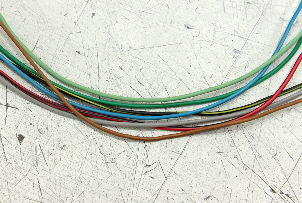
I also grinded lenses of LEDs and made their ends flat, then I polished them. This operation made LEDs less bright but more suitable for my design. Next question was wires. Here is my very personal opinion on wiring question: always use wires of colours which fit wiring of motorcycle you are working on. If Kawasaki Zephyr 750 wiring “use” black/yellow wire for ground, so will I, and so on, and so forth. And if I am about to include in wiring feature that wasn’t there before, I will use the wire of colour that couldn’t already be found in wiring. This is the only way to avoid mess.
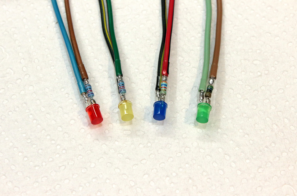
 I am definitely not the best with soldering iron, but at least I try to solder components securely and accurately. Here is result of my work, places of soldering and resistors already packed into transparent heat-shrink tubing.
 Second tubing went through the indicator housing.
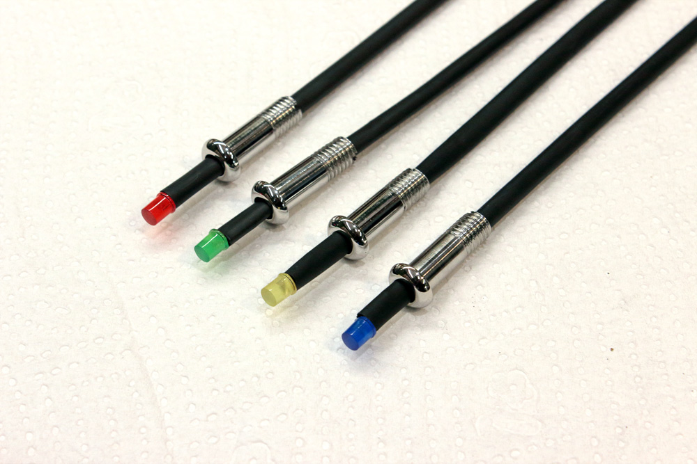 I fixed LEDs and tubing in housing with transparent epoxy. This will make indicators weather protected.
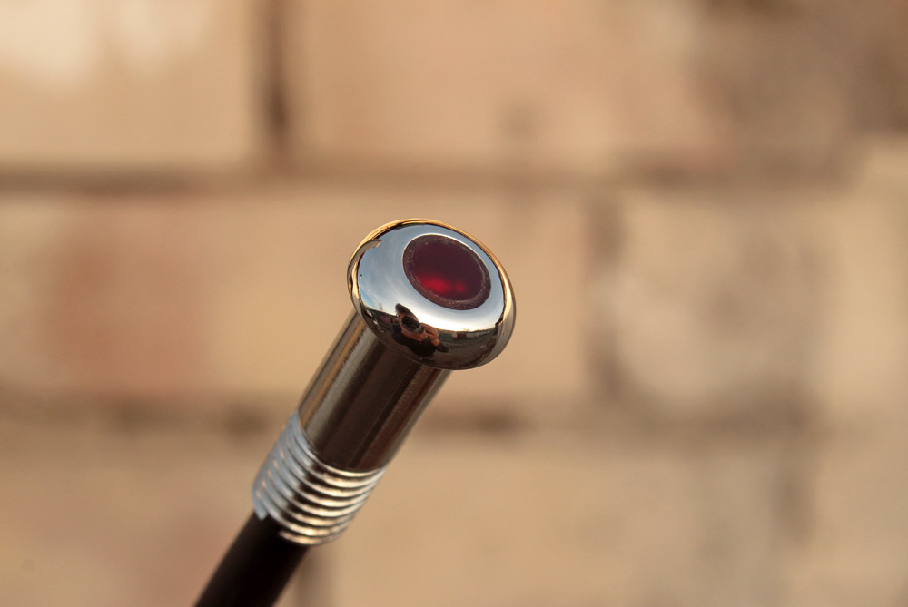
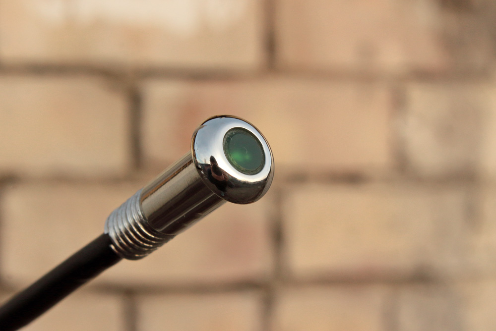
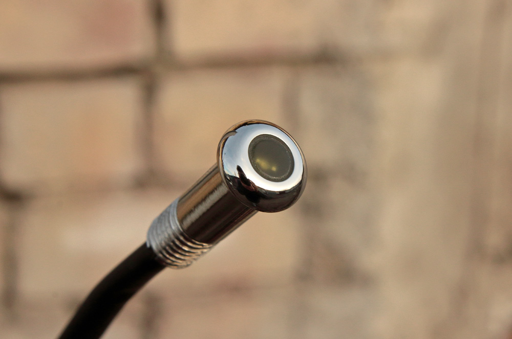
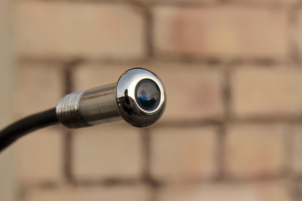
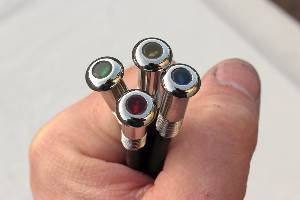 Result looks quite nice: