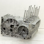
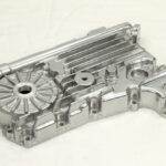
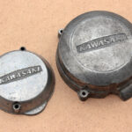
When I was checking if I have all necessary parts for the Kawasaki KZ650 engine assembling, I also checked the fitment of all aftermarket gaskets. After that I decided to buy an OEM oil pan and transmission/gearshift cover’ gaskets. Since I already have OEM cylinder head and cylinder base gaskets, this means that I am about to use aftermarket gaskets only for clutch cover, valve cover, alternator cover and ignition cover. Last two are least critical and clutch and valve covers are easy to replace. So all “significant” gaskets will be genuine/OEM.
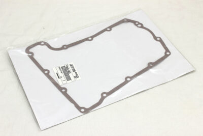
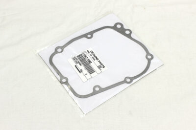 Along with gaskets I received front tank rubbers and some other goods (later have no connection with KZ project).
 Next part of the story is more complicated and educational.
Later type of Kawasaki KZ650 crankcase (starting from C3 and B3 models) has a secondary shaft bearing’ stopper plate with three holes and the crankcase has three corresponding holes for that plate. Two of these points also serve for oil pump mounting and only one serves solely as plate mount point. Crankcase also has an additional hole that serves as the third mount point of the oil pump. In this way the total quantity of holes used to fit the secondary shaft bearing stopper and oil pump is four.
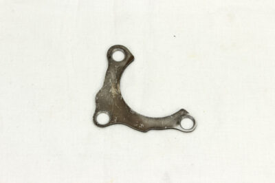
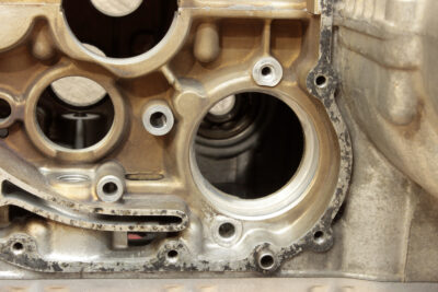
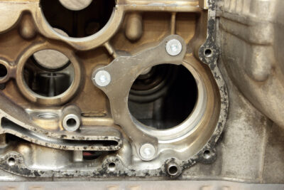 This design of stopper plate became classic and was inherited by all Kawasaki 750 inline air-cooled fours: KZ750, GPZ750, Zephyr 750 and ZR7. But it was not always like that. The earliest secondary shaft bearing stoppers also had three holes for mounting, but unlike later plates only one of the holes was simultaneously used to hold the plate and oil pump. Two holes in the crankcase served solely for oil pump fitting and another two – solely for stopper plate fitment. This gives us a total of five holes for the stopper and pump. The earliest type of bearing stopper could be found only in the earliest service manual (1976) and I could assume it didn’t come into series.
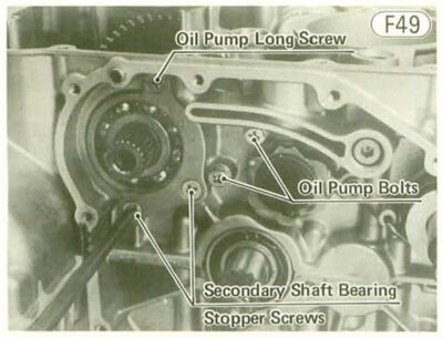
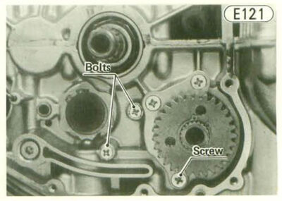 Kawasaki KZ650 of B1 and C1 models came with secondary shaft stoppers of different design. Total quantity of pump and stopper holes was similar to pre-serial crankcases (five), but the number of holes in the stopper plate were increased to four. Of these two holes served to secure the plate itself and two were used also for the oil pump mount. I could assume that along with this change of design also came a notion in the OEM service manual to stake stopper screws heads with punch to prevent them from loosening. Thus, the reason for such change is pretty obvious: the secure fitment of the oil pump. Even with one bolt loose it still was securely fixed by two staked screws (both of which go through long dowel pins).
However, four holes in the stopper plate was overkill, since three points are enough to determine a plane (and fix it as well). Thus, no wonder that in later models (starting with C3 and B3) Kawasaki got rid of the fourth screw and its holes in both crankcase and stopper plate.
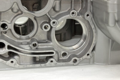
At some point I noticed that crankcase I bought for project is of early type:
 Sure, I could have used stopper plate of later type without issues:
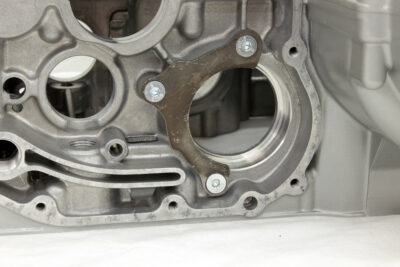 But it turned out that I couldn’t stand the idea of leaving that fourth hole without a screw and covered by plate… So I dug information a bit deeper (including scans of OEM parts lists with original, not yet superseded parts numbers) and that’s where I found that the design of the secondary shaft bearing stopper plate was changed not three, but four times. The earliest serial stopper had part number 14014-038 and was pretty hard to find. It arrived to me being still wrapped in remains of OEM packaging:
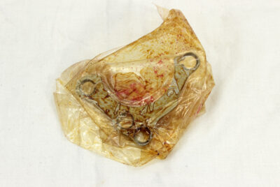 And here is this early stopper itself:
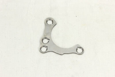 As you may see it has cut-outs for staking and it’s likely it could be reused without indication of how many times screws were staked.
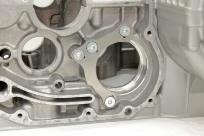 At some point it was replaced by less-effortful-in-manufacturing plate without cut-outs for staking. It turned out to be less hard to find and fetch.
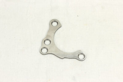
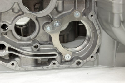 Funny thing: part 14014-038 number was superseded by 14014-1007, but there are no traces of further changing of part numbers. So it looks like the second serial type of stopper plate changed its design to the third without change of part number. But it’s not the first time that such a replacement was made by Kawasaki.
And here are all three models of serial stopper plates side by side, from earliest to latest.
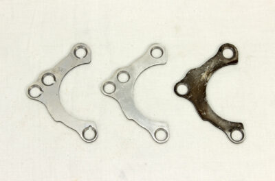
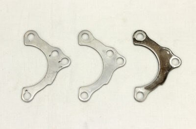 Their outer shapes are completely identical:
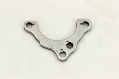
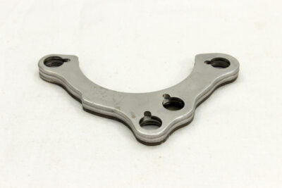 I like to find out things like this: you see the thread, you pool it and the whole story unfolds before you. In this case it is the story of one part and the reasons due to which part’ design was changed four times in a matter of a couple of years.

