Let’s start section about project wiring, electrical components placing, cable routing and tank mounting.
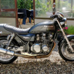
To make sure I get all hp and Nm from the Honda CB750 Seven Fifty engine, modified with CBX750 cylinder head and camshaft I decided to use CBX750 ignition unit and wiring. As it written in CBX750 sale brochure: “Next on the list of no-maintenance features is the transistorized, pointless ignition. It even features a power-boosting electronic advance mechanism and built-in over-rev protection”. I also like design of CBX750 handlebar switches with all those yellow markings. In the same time I had intention to use some modern parts from Seven Fifty, like rectifier, ignition coils and starter relay.
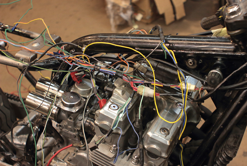
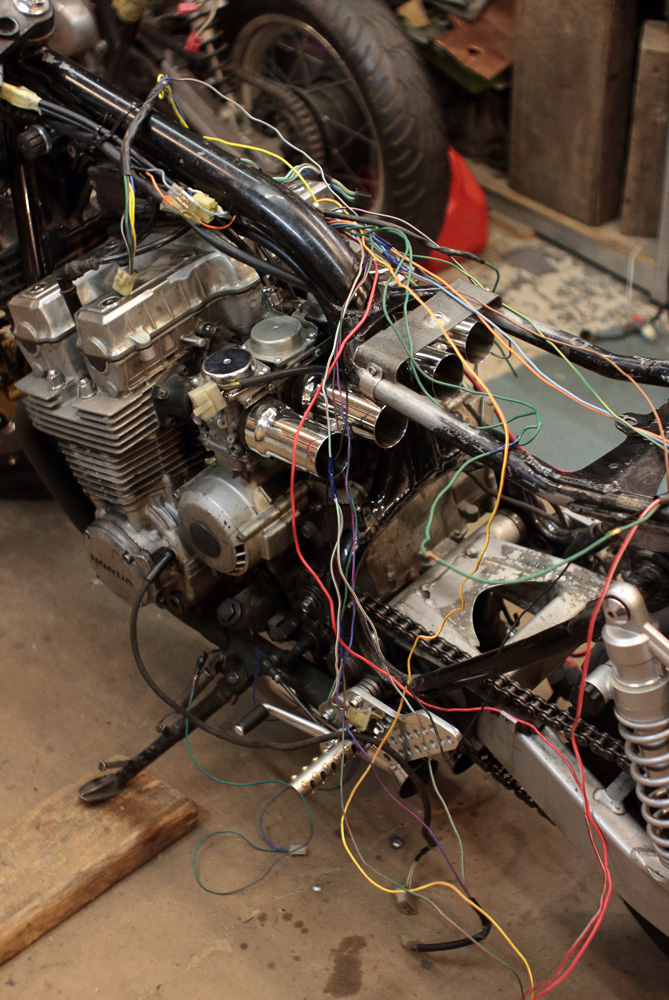
CBX750 is a motorcycle from the eighties, when clocks looked like starship dashboards with all kind of meters and indication lamps. It even had indicator for tail lamp malfunction. This motorcycle is also clad in full fairing, so as result its wiring looks like the Nessy, suddenly surfaced in the full length.
 So I had to shorter it and simplify it. I printed colour schemes of wirings and began the work:
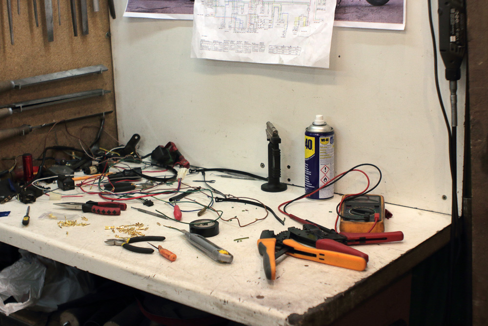
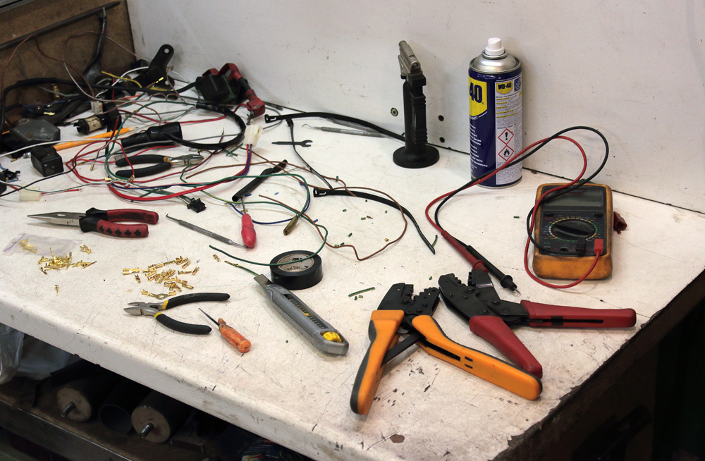
 It is always messy when I work on wiring: tables piled with wires, connectors, insulating tape, heat-shrink tubing, wire cutter, knifes, crimping pliers and other stuff.
 But soon after start I realized that firstly I had to:
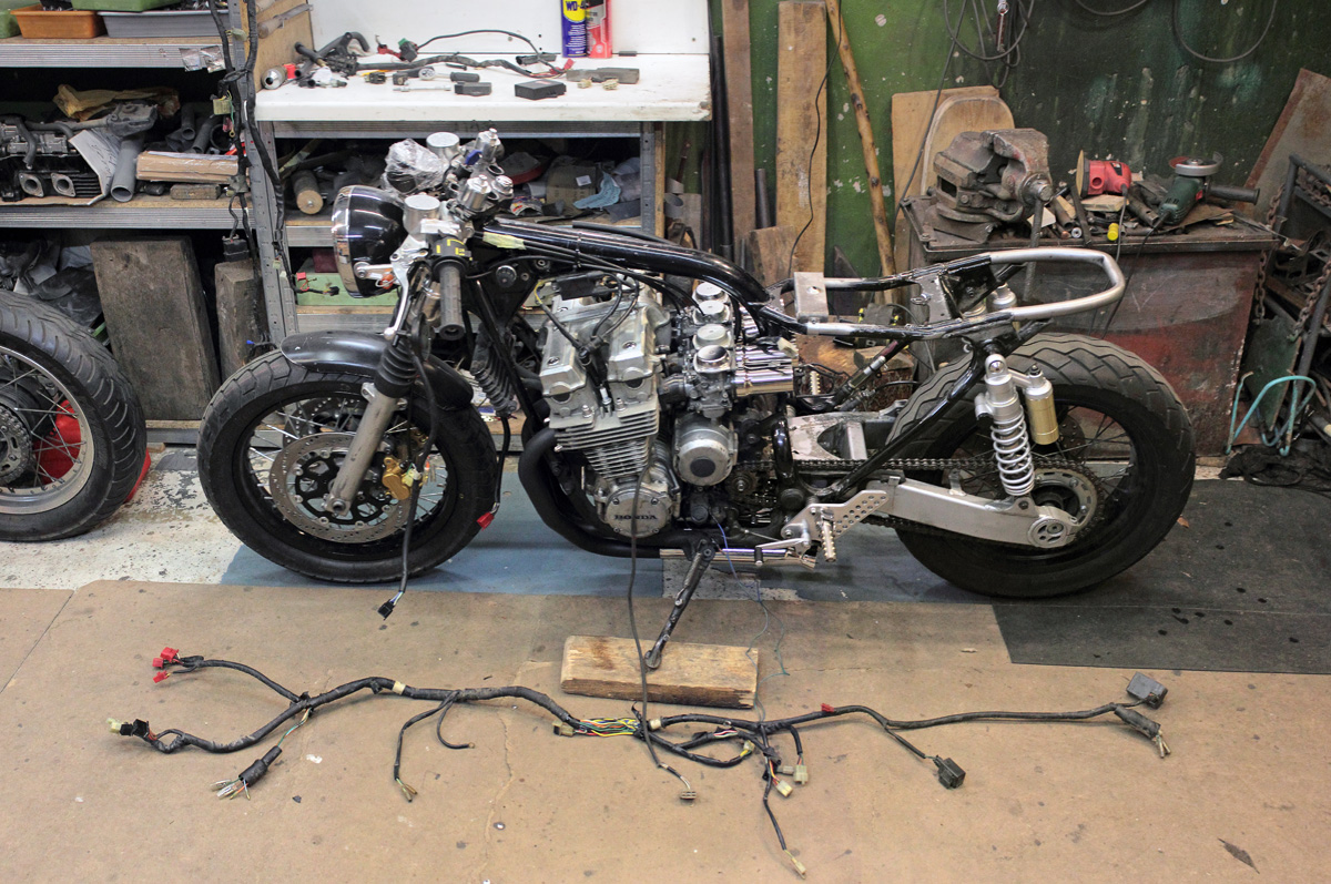
- Replace temporary tank mounts with permanent.
- Establish positions of main components of the system (a battery, an ignition unit, a rectifier, a starter a relay, a signal, a fuse box, a horn)
I designed the rear mount plate for tank and made it of 2mm steel.
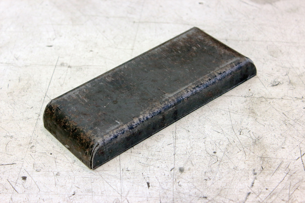
 As tank mounts to the plate at an angle, I tapped mount point similarly to Honda original one. The mount was welded and I grinded it.

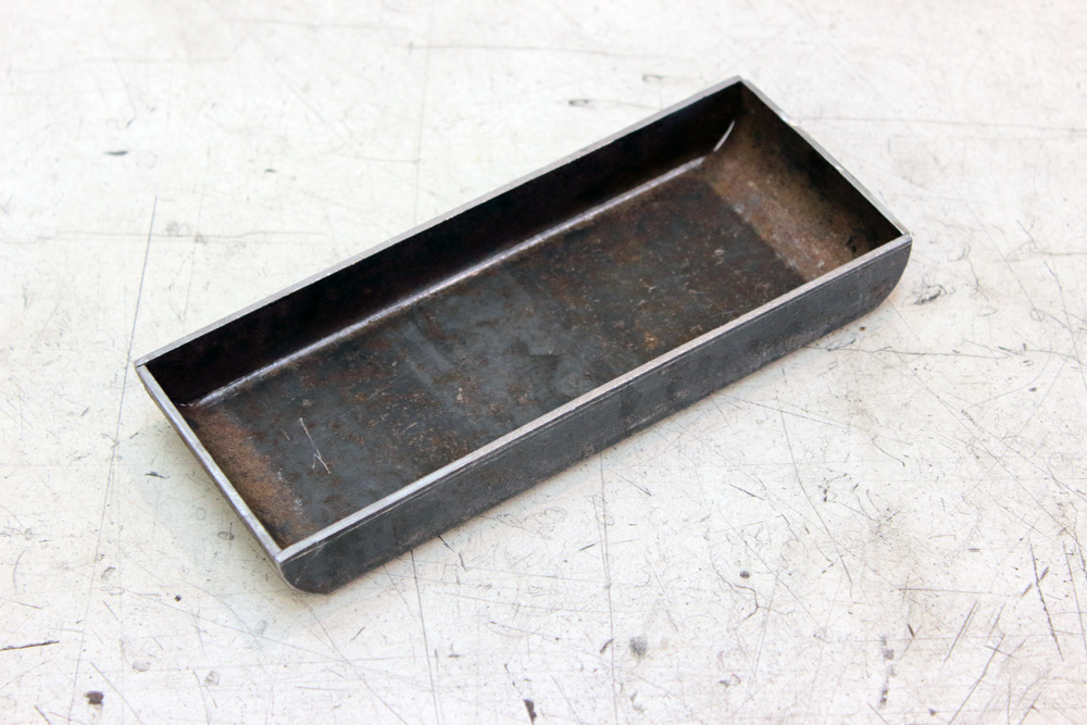
 Front mount points were simpler to make:
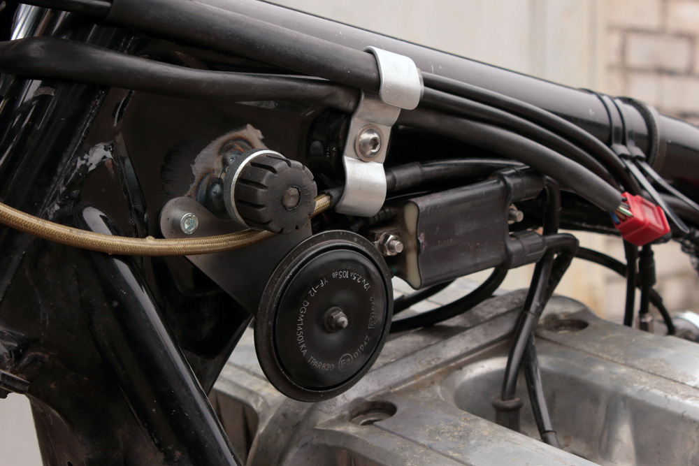
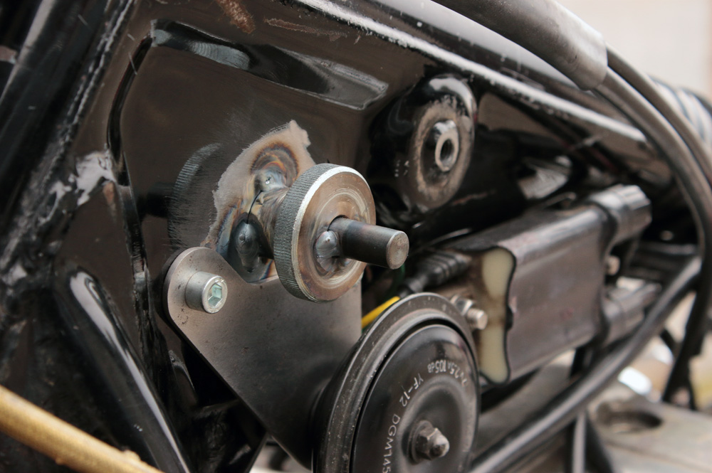 As you may see, their position is right where relay rectifier was, so I had to move it somewhere, but a blessing in disguise, so rectifier mount points turned out to be good place for horn mount. That’s how all it looks when assembled. You may also pay your attention to the bracket which fix throttle cables, right handlebar switch wiring and clutch hose.
How I managed the question of battery I wrote earlier here>>
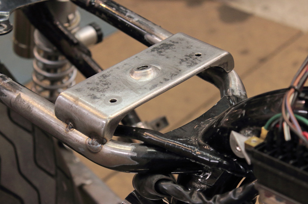
When I was working out design of rear tank mount bracket, I pursued three goals: tank mount itself, seat front mount and ignition unit mount in addition. So that’s how bracket looked when it was initially welded to the frame:

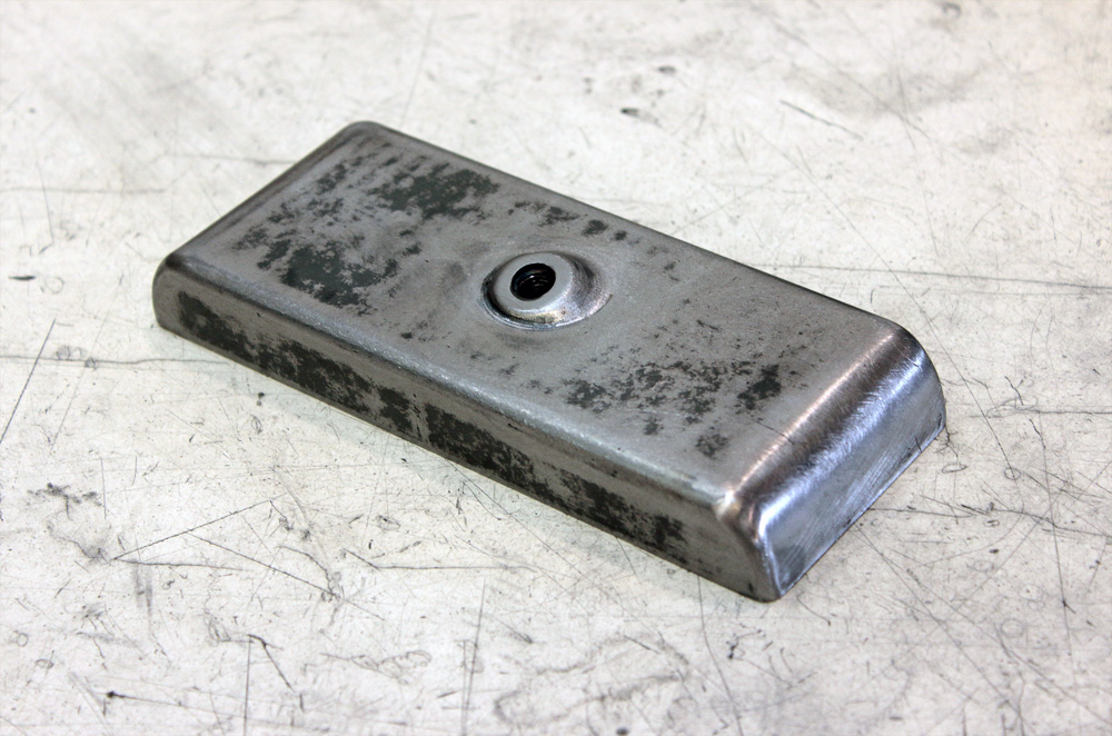
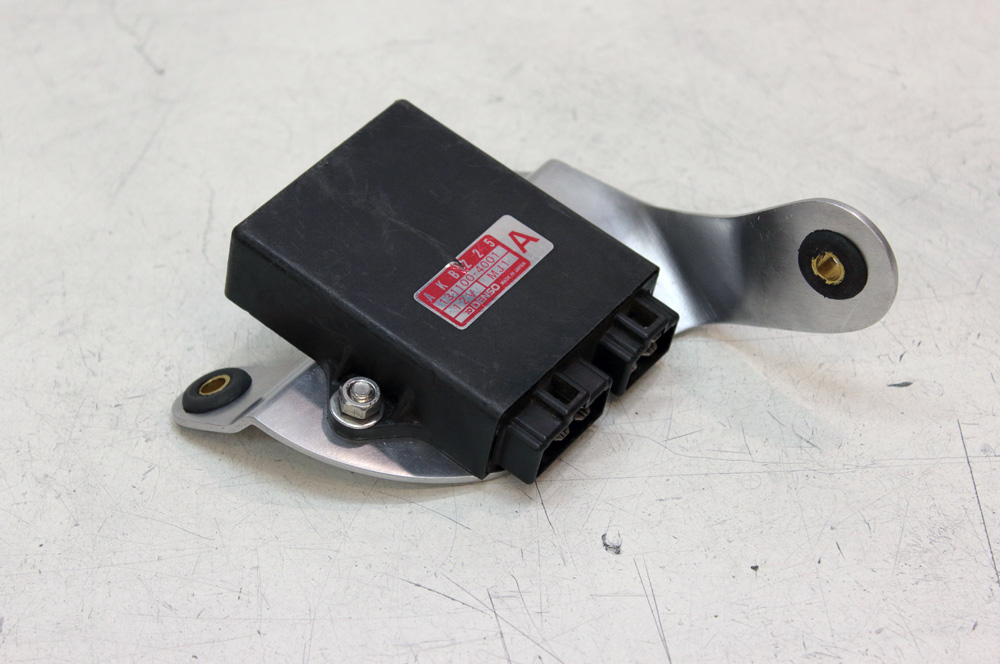
 Ignition unit bracket I made of aluminum and equipped it with rubber bearings to kill vibration.

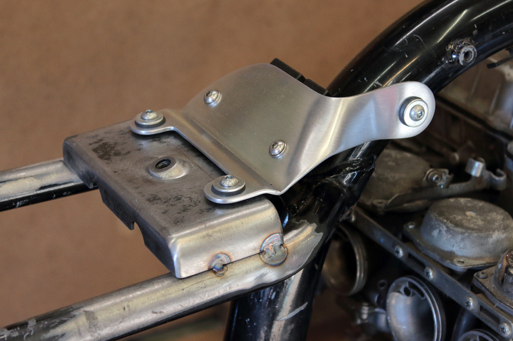
 That’s how it looks on its place:

 The pieces of the puzzle began to click into place.
To be continued.